Introduction#
The aim of this book is to learn the basics of x-ray transmission physics and imaging.
Radiological images, historically implemented for testing welds (Fig. 1) and castings (Fig. 2) are easily interpretable. The grey-value in the radiological image is directly related to the attenuation of the X-ray beam: transmission imaging is the very principle of radiology. Since the information is based on attenuation, the radiological testing of thick materials which may block completely the beam can be very difficult to perform.
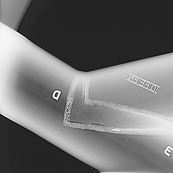
Fig. 1 V-shape weld#
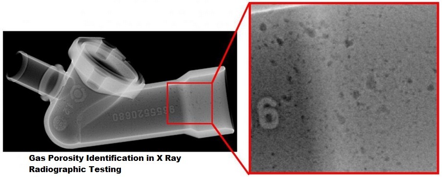
Fig. 2 Gas porosity#
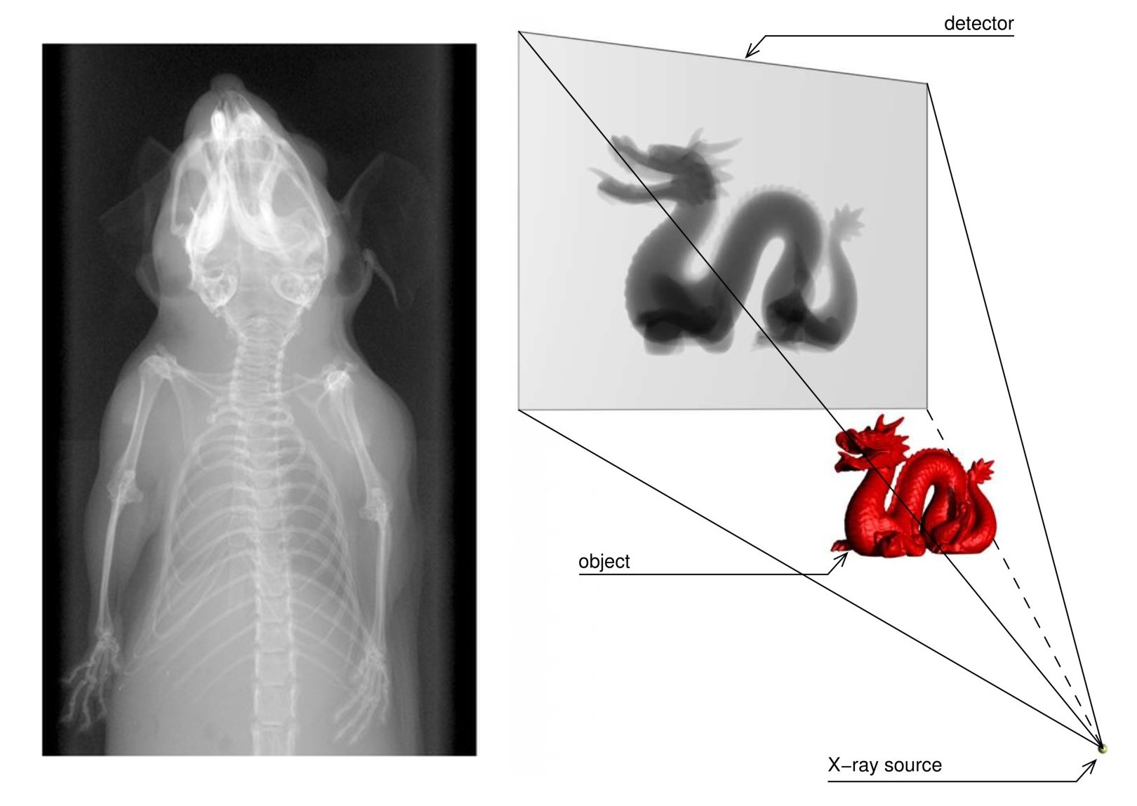
X-ray imaging is analogous to a projection, which means that the third dimension (depth) is not accessible from a single radiography. We do not know what part is in front or behind in the x-ray images.
On this rotational radiography (Fig. 3) of a tire we can see the folds of the structure net. The tire ruptures of large construction machinery could be very dangerous, and the testing for defects is critical.

Fig. 3 Tire structure#
X-ray tomography is widely used to inspect in three dimensions inside the part to be tested. The reconstructed volume is therefore a 3D image of the attenuation coefficient for the X-rays. In Fig. 4, the lighter the grey value the larger the attenuation coefficient.
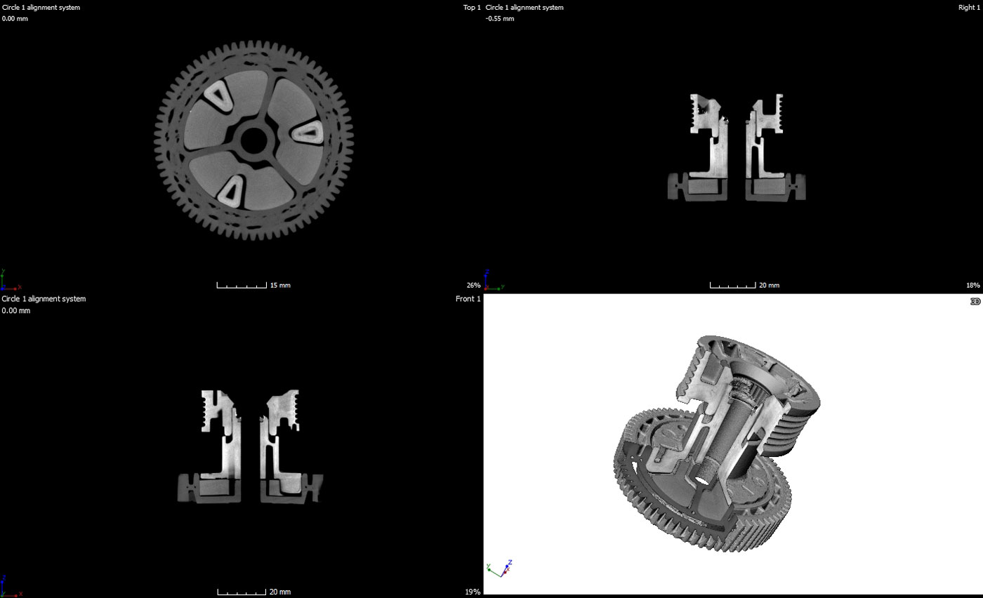
Fig. 4 Computed Tomography on Gear#
Fig. 5 shows an application of radiography for thickness measurement of pipe walls. Metrological software is usually distributed along with the x-ray equipment. Application in dimensioning and metrology of surfaces after reconstruction and segmentation of the volume to extract the isosurface (Fig. 6). Study of compliance with the specifications of a prototype by comparison with a CAD volume (Fig. 7). More example can be found in some x-ray systems manufacturer sites, eg Nikon Metrology.
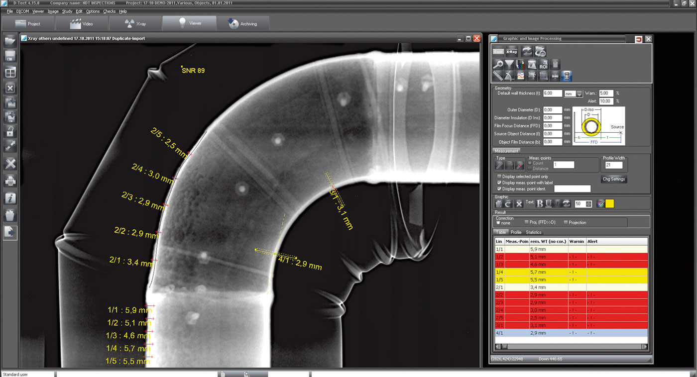
Fig. 5 Pipe wall thickness#
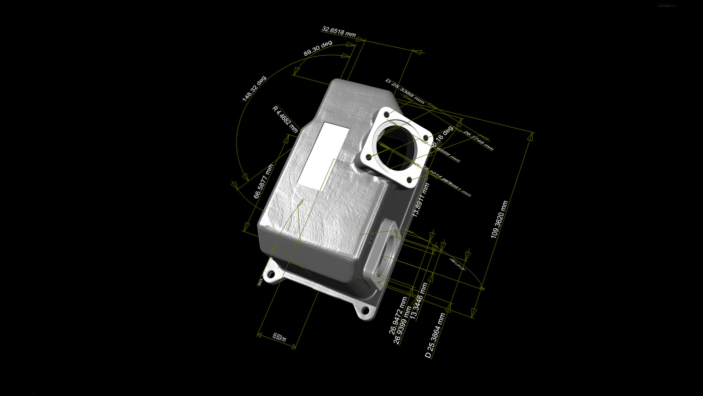
Fig. 6 First article inspection#
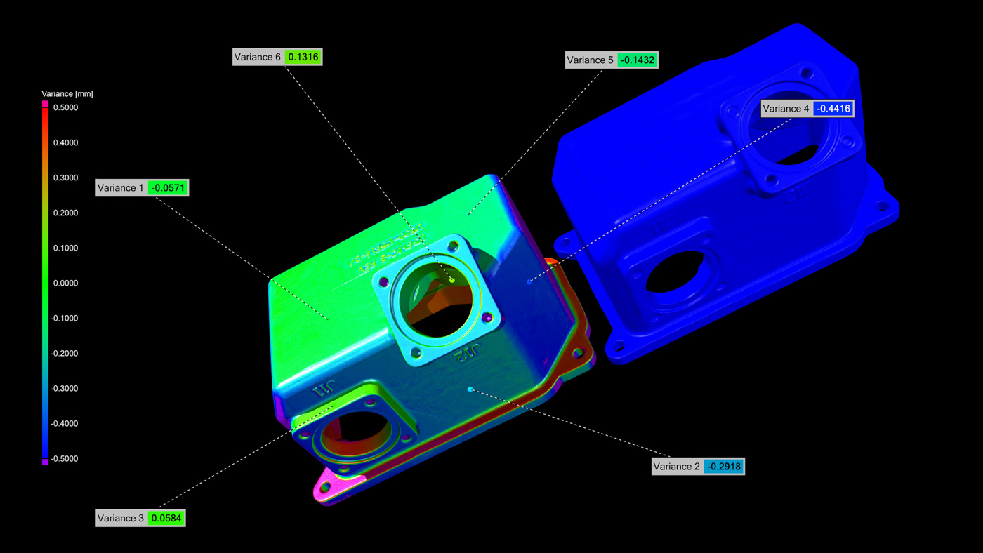
Fig. 7 Part-to-CAD comparison#
X-ray image formation is therefore similar to a cast shadow. The image obtained presents necessarily a magnification (\(M>1\)), because the x-ray optics are very delicate to set up in industrial environments (the x-ray beam diverges simply from the source). Attenuation increases with the thickness \(X\) of the part, with the density \(\rho\) and the atomic number \(Z\) of the material. We can also note that the spatial resolution will be essentially conditioned by the detector and the experimental protocol – ie the apparent pixel size given the magnification – and not by the wavelength which is very much lower than the micron.