Defects#
Protocol for taking an X-ray with the image quality indicator (IQI) which allows to appreciate the resolution spatial.
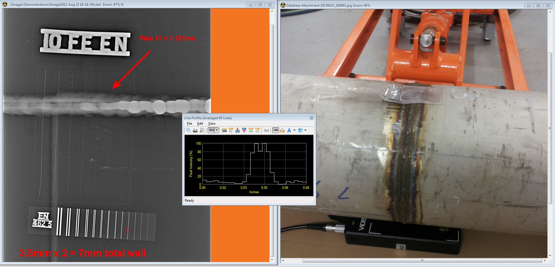
Fig. 129 Image Quality Indicator#
Examples of radiographs illustrating for some pictures difficulty in locating in space or ambiguity of interpretation.
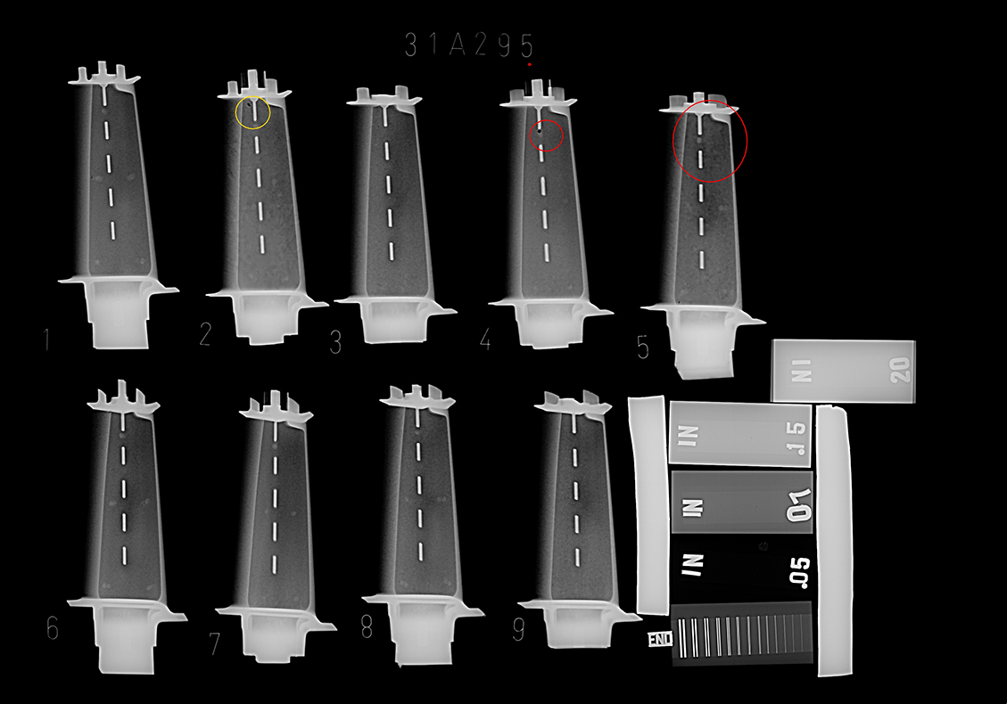
Fig. 130 Jet engine blades castings#
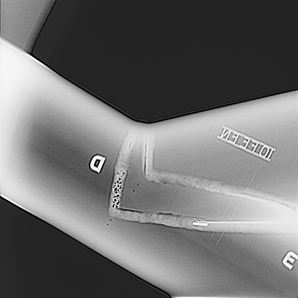
Fig. 131 V-shape weld tapping#
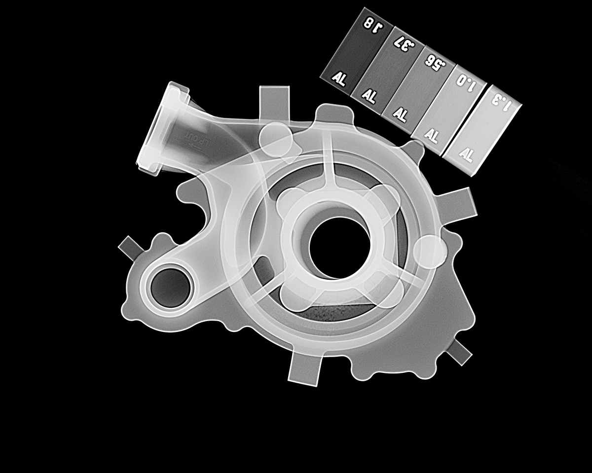
Fig. 132 Aerospace Al Casting#
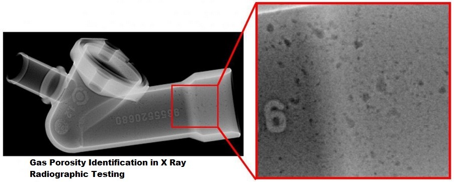
Fig. 133 Gas porosity#
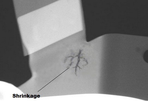
Fig. 134 Shrinkage#
ASTM reference snapshots listing the severities of various defects in aluminum casting
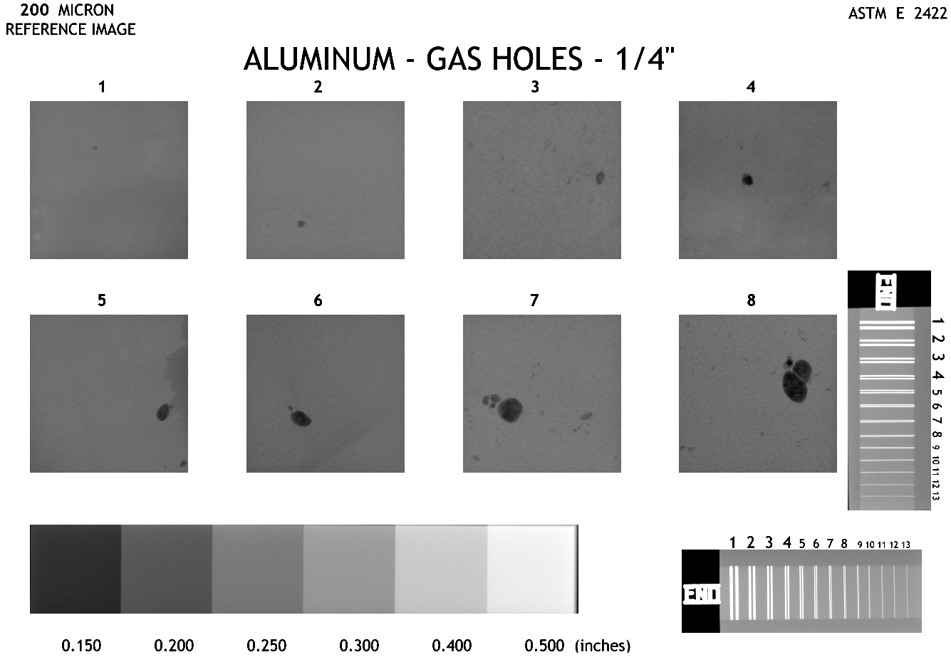
Fig. 135 ASTM E2422: Standard Digital Reference Images: Gas holes#
_1_4_200micron.png)
Fig. 136 ASTM E2422: Standard Digital Reference Images: Gas porosity#
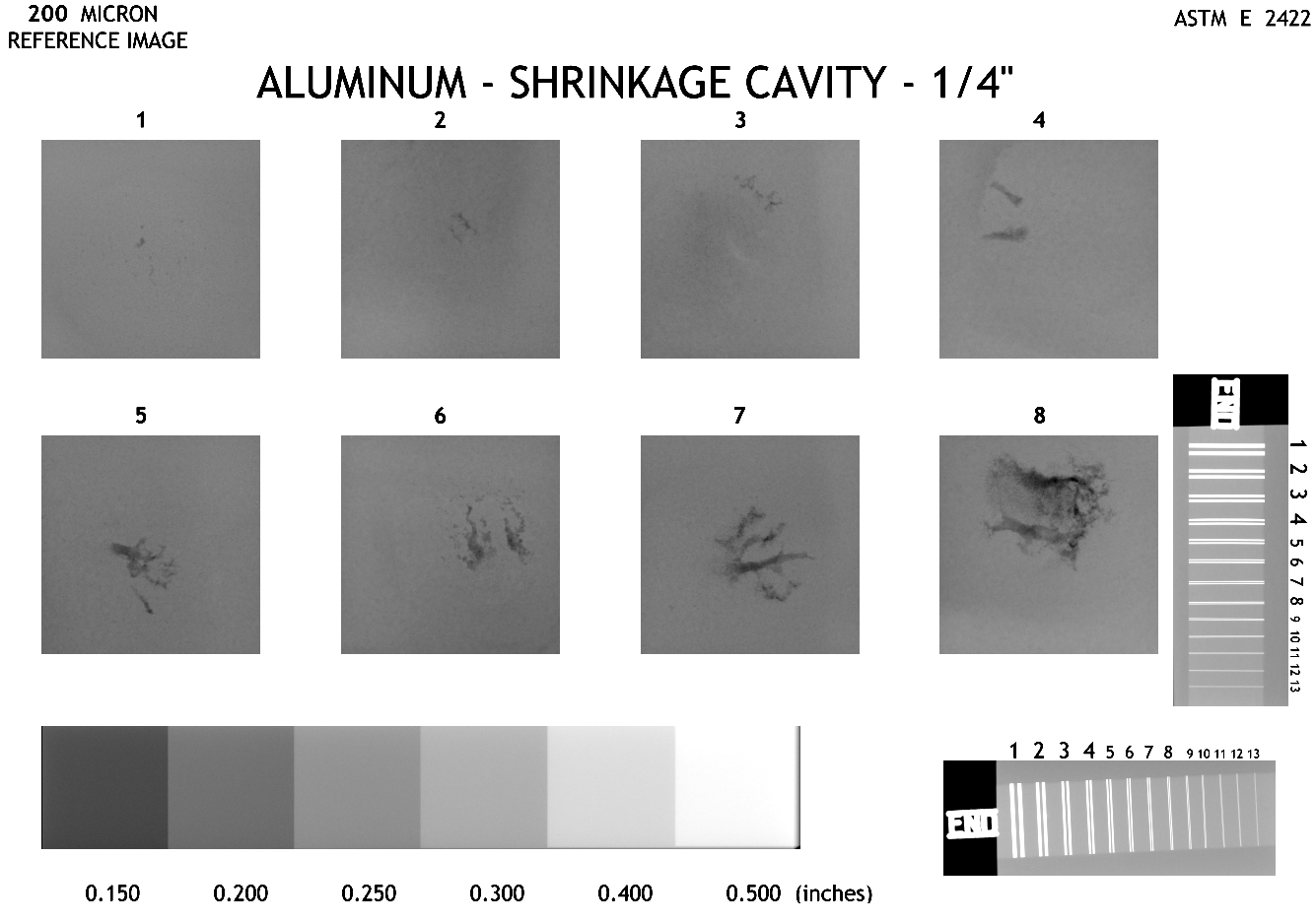
Fig. 137 ASTM E2422: Standard Digital Reference Images: Shrinkage cavity#
Illustrations of typical defects in welds.
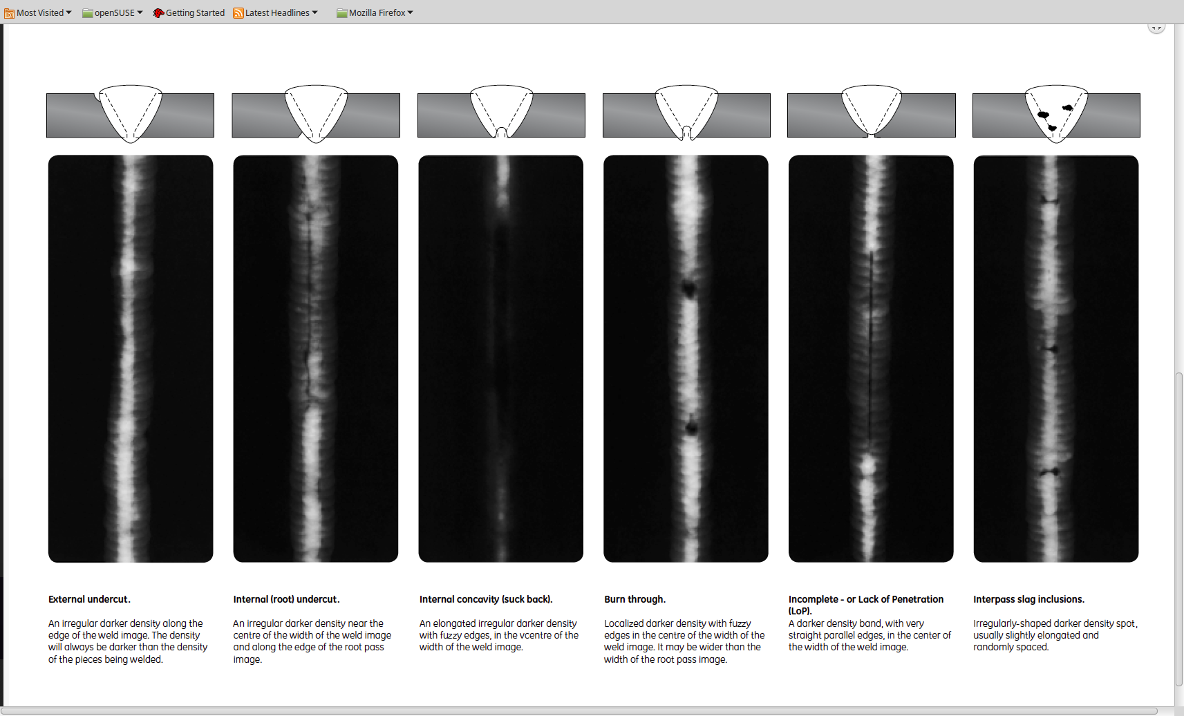
Fig. 138 Reference radiographs: welds#
The detectability of a crack is only possible if the direction of X-radiation propagation is tangent to the plan (without which the crack will be invisible because showing no difference in attenuation for the radiation), and it must also have an opening quite pronounced.
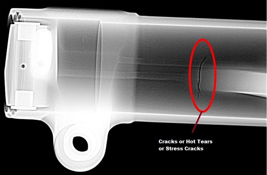
Fig. 139 Hot tears stress cracks#
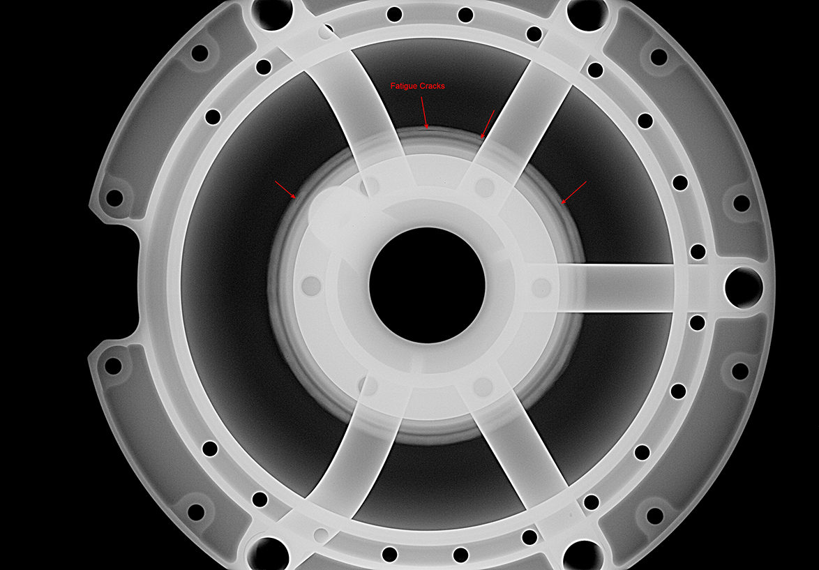
Fig. 140 Aerospace cast oil tank cover: fatigue cracks#